Monthly Archives: January 2019
- January 31, 2019
Elastomer Technology in Mechanical Seals
Evaluate properties of rubber during installation and seal life.
Elastomers (or rubbers) are a ubiquitous family of materials whose use stretches across nearly the entire range of mechanical seal designs. From plant-sourced natural rubber, so named by John Priestly in 1770 for its utility in rubbing away pencil graphite, to petroleum-sourced synthetic rubber first developed around the turn of the 20th century, the "elastomer" and their properties are familiar but should not be overlooked—especially when dealing with mechanical seals.
How Elastomers Work in Mechanical Seals
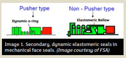
Rubber seals come in a variety of profiles—O-rings, cup gaskets, bellows diaphragms, sealing/wiper lips and many others. They are classified as either static or dynamic and create positive pressure
against surfaces to eliminate or control the leakage of liquids and/or gases while preventing the entrance of external contaminants such as dust and dirt. Static sealing occurs between adjacent surfaces with no relative motion, such as between the pump casing and cover. Due to frictional wear and heat generation, dynamic sealing is less straightforward, occurring between adjacent surfaces that are continuously or intermittently moving relative to another, such as between the pump casing and shaft.In mechanical face seals, elastomers tend to take second chair because the primary seal—the dynamic seal between the housing and rotating shaft—is achieved by sliding contact between the pair of stiffer, lapped-flat sealing faces, one stationary in the housing and one rotating with the shaft. In many designs, rubber provides the secondary seal between each seal face and adjacent surface. One seal face is fixed and sealed statically using an O-ring or cup gasket. The other is spring-loaded and requires a semi-dynamic seal to accommodate some axial play, such as a dynamic O-ring in pusher-type mechanical face seals or elastomeric bellows in nonpusher ones. These semi-dynamic applications (involving flexing and sliding of the elastomer) can be critical for maintaining proper contact between the faces through face wear, shaft movement, etc.
Although the seal face pair tends to be the most critical design feature, mechanical face seals are often used in the most demanding applications.
Rubber technology features prominently in radial lip seals, where typical applications have lower pressurevelocity (PV) values relative to those involving mechanical face seals. Still, the flexible elastomer lip must handle considerable relative motion in the form of shaft/bore rotation, reciprocation or a combination of both. In addition to standard designs and sizes, numerous customizations and proprietary approaches exist. The simplest designs rely on a single rubber lip’s inherent resiliency, although common enhancements include multiple sealing lips, a circumferential garter spring installed in a groove over the sealing lip to maintain contact with the shaft, and an auxiliary wiper lip or “excluder” to prevent abrasive dust or debris from compromising the primary sealing surface. For improving service life and performance in rotary applications, unidirectional or bidirectional hydrodynamic pumping aids can be added in the form of custom-shaped extrusions on the backside of the sealing lip to return leaked fluid to the sealing interface, increase lip lubrication and lower operating temperatures.
Benefits of Rubber
The definition of an elastomer provides initial insight into where rubber gets its resilient sealing quality: “a macromolecular material which, in the vulcanized state and at room temperature, can be stretched repeatedly to at least twice its original length and which, upon release of the stress, will immediately return to approximately its original length.”
When the rubber is squeezed by the adjacent surfaces of the clearance gap to be sealed, it has the characteristic
properties of malleably deforming and taking the shape of each surface in response to the stress and applying a force back against the surfaces in its attempt to return to its original dimensions. Elastomers consist of large molecules called polymers (from the Greek “poly” meaning “many” and “meros” meaning “parts”), which are long chains of the same or different repeating units, called monomers, usually linked together by carbon-carbon bonds (the
most notable exception being silicone elastomers, which are linked by silicon-oxygen bonds). Soft and hard plastics are also composed of polymers. However, the regularity of the monomers in their polymer chains allows neighboring segments to align and form crystals, making the macromolecular plastic material rigid and inelastic.One can prevent this crystallization by breaking up the regularity of the polymer chain, resulting usually in a viscous “gum” that is readily shaped into molds. At the molecular level, the polymer chains are similar to spaghetti-like strands flowing past each other.
During the process of vulcanization, or curing, the viscous liquid is heated with sulfur or peroxides and other vulcanizing agents, and crosslinks form between polymer chains, tying them together with chemical bonds, converting the gum into an elastic, thermoset solid rubber that retains its shape after moderate deformation.
In addition to the selection and preparation of base polymer(s) and cure system ingredients, formulating the final rubber product, also known as compounding, involves five other broad categories of ingredients, which have percentage compositions expressed in parts per hundred rubber (phr). Fillers include various powders that thicken the polymer mixture, improve strength and resistance to abrasives, and reduce final cost. Plasticizers are oils and other liquid hydrocarbons that lower viscosity to ease processing, soften the final compound and in some cases improve low temperature performance. Process aids are specialized chemicals added in low concentrations to improve mixing, flow properties and final appearance.
Antidegradants protect the rubber from environmental attack. Finally, various miscellaneous ingredients may be added for special purposes, including foaming agents, dyes, fungicides, flame
retardants, abrasives, lubricants and electrically conductive particles. A simplified description of processing these ingredients includes mixing via tangential or intermeshing mixers, forming into desired shapes and vulcanizing into the final product. - January 29, 2019
Expansion Joint Control Units
Elongation settings are a vital factor to assembly effectiveness.
It is no secret that one of the greatest demands for an expansion joint is the expectation to serve a long, leak-free life with little-to-no maintenance. Once installed, these flexible rubber connectors should require little attention. The preservation of this investment (and one’s sanity) can be maximized with an in-depth overview of how control units can prevent a new expansion joint from being overstressed.
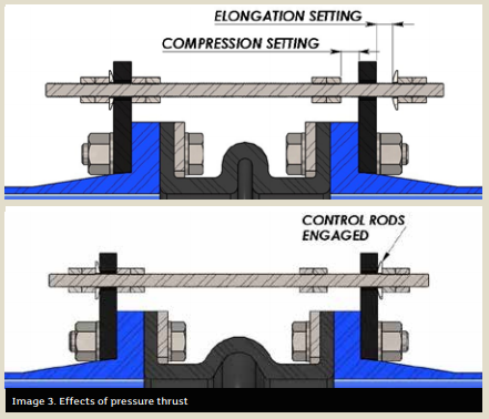
The purpose of a control unit is to act as a safety device against excessive movement resulting from pressure thrust. A typical control unit assembly is comprised of threaded rods, steel gusset plates, nuts and washers (see Images 1 and 2).
The usage of control units with an expansion joint is always beneficial; pressure spikes during a system upset can cause uncontrolled surges through the expansion joint. This is a prime example of how valuable it is to have control units installed to protect these rubber assets from damage.
Methods to the Madness
A common misconception about control units is that they are designed to support the weight of pipe members or act as a substitute for adequate mounting. They are not. The sole purpose of a control unit is to allow the expansion joint to move freely within a specific range of movement while preventing the joint from being overstretched from pressure thrust forces.
The control units in no way impede the joint from performing its other duties beyond movement (vibration absorption, cycling or compensation for misalignment). The few extra steps needed to install the control units with the expansion joint could pay notable dividends in the long run.
Pressure thrust plays a huge role in how an expansion joint functions. While under pressure, the forces acting on the inside walls of the expansion joint actually cause the joint to swell and elongate. In the real world, an expansion joint is held comfortably between two pipe flanges, which in most cases are restrained by a pump lagged to the floor or mounted to a structural beam. Although it may not be apparent to the naked eye, once the expansion joint sees pressure, it produces a thrust force that acts axially on both pipe flanges.
Theoretically, what would be the result if the expansion joint was unrestrained on each end while pressurized?
Without fixed ends, the pressure thrust would force the joint to elongate without bounds.
Most useful in high pressure applications, the control rods will engage with the gusset plates once a pre-specified amount of growth for the expansion joint has been reached, restricting the joint from stretching any further. At this point, the control rods are absorbing any additional thrust acting on the pipe flange, thus limiting the amount of stress that is exerted onto adjoining equipment.
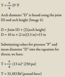
The design theory for sizing control unit hardware is based on the pressure thrust. Nominal inside diameter (ID) and arch geometry of the expansion joint are key drivers for calculating the thrust force that will be applied to the pipe at maximum line pressure. Per
industry standards set by the Fluid Sealing Association (FSA), both control rods and gusset plates are designed to withstand no more than 65 percent of the yield strength of the material.
Magnitude of the pressure thrust can be calculated by knowing the internal pressure and the effective area of the expansion joint. Effective area is found using the arch diameter of the expansion joint, which takes into account the size of the arch.
For example, we can calculate the resulting pressure thrust for a 10-inch ID expansion joint using an arch height of 1.5 inches that is rated for a maximum pressure of 250 pounds per square inch (psi).
The equation for pressure thrust “T” is:
These design limitations based around yield stress are the reasons why some control units made from lower yield strength stainless steel contain thicker components or more rods per set than the standard carbon steel control units.
Installation & Inspection
For a control unit assembly to be effective, rod positioning and elongation settings are critical during installation. Each control rod should be evenly spaced around the flange to best distribute the load. Elongation settings (see Image 5) are often overlooked, yet are a vital factor to ensure the control units fulfill their intended use.
Every expansion joint comes with movement ratings based on arch size, configuration and number. These movement design ratings of the expansion joint are critical pieces of information that are absolutely required during the installation of control units. The general rule of thumb is the gap between the gusset plate and the nut should be adjusted to match the joint’s elongation rating.
Having this information at hand during installation is great, but what about the existing control units currently in operation? Visual inspections of these components are a basic task that goes a long way toward extending the life of the joint.
Here are the top 4 anomalies to look for when performing a field inspection:
- January 24, 2019
Gallagher Fluid Seals helps meters & instruments manufacturer through the design and fabrication of a custom-molded gasket with an engineered profile.
The Problem
Our client’s micro corrector was experiencing water intrusion past the gasket, caused by improper seal material and configuration.
The Approach
Gallagher Applications Engineer Benjamin Mell worked closely with our client to identify & address the issue and suggested sending a sample of the instrument to GFS headquarters. Our engineering team received the hardware and investigated the root cause of the seal failure.
GFS engineers observed that our client’s closed-cell
- January 22, 2019
Food Safety Modernization Act (FSMA)
Every year, nearly 1 in 6 people in the U.S. get sick (~48 million people), 100,000+ are hospitalized, and 3,000 die from foodborne illnesses or diseases, according to data from the CDC. Though this is largely a preventable problem, it still poses a significant public health burden.
The FDA Food Safety Modernization Act (FSMA), enacted by Congress in 2011, is "transforming the nation’s food safety system by shifting the focus from responding to foodborne illness to preventing it."
Although one might think the relevancy of the FSMA is more geared towards the food or beverage product itself, this act is actually vital to the processing operations in food, beverage, and pharmaceutical industry.
Over time, exposure to continuous vibration, volatile temperatures, and corrosive chemicals can cause O-rings in processing operations to become worn and eventually fail. When this occurs, particles of rubber from seals and gaskets can shear-off and migrate through sanitary systems, piping mechanisms, or by other means, eventually entering the product stream.
In some cases when a problem is discovered, equipment must be shut down and visual inspections conducted to find the source of contamination. This leads to downtime, lost production, and lost revenue. If the contaminant ends up in the supply chain, even more risk is assumed due to recalls or litigation.
Enter the metal detectable O-ring.
- January 17, 2019
Article re-posted with permission from Parker Hannifin Sealing & Shielding Team.
Original content can be found on Parker’s Blog.Contact GFS about battery sealing solutions >>
Sealing can often be a frustrating challenge when dealing with batteries and battery storage solutions. Determining what materials are compatible with certain chemistries or developing a profile that provides optimal sealing under available compression can be a time-consuming task for those outside the sealing industry. A trial and error approach can have a significant overall cost impact through multiple prototype iterations, prolonged testing, and ultimately, delaying product commercialization.
Specialized support
With Gallagher Fluid Seals and Parker Sealing's design and material engineers, we can provide support to your team in the critical, early stages of product development. With hundreds of engineered elastomeric materials to choose from, Parker and GFS can identify and recommend a compound that works with your specific electrolytes or other fluids. With the exceptionally long lifetime requirements of flow batteries, Parker's homogeneous rubber provides the elasticity needed to handle the many charge-discharge cycles the battery will see in its life.
- January 15, 2019
Installing Radial Shaft Seals
Radial shaft seals, also known as lip seals, are used to seal rotary elements, like a shaft or rotating bore. Hydraulic pump seals, axle seals, valve stem seals, or strut seals are the most common examples the average person would recognize.
Radial shaft seals are used in a variety of applications and perform two essential functions: the first is to avoid leakage through retaining the bearing or system lubricant; the secondary function is to avoid the contamination of the system by outside impacts (external particles or environmental issues).
- January 14, 2019
Over-tightening, excessive speed and improper installation can cause a system to falter.
In many respects, troubleshooting and failure analysis of compression packing materials is similar to the investigation of a crime scene. A good investigator knows how to gather clues from many different sources and put them together to understand what has happened. A good troubleshooter uses the same information gathering method, familiarizing themselves with the sealing materials, the process equipment and the systems where they are used.
Start by Interviewing Witnesses
The troubleshooter should seek information from the people who work with the equipment on a regular basis. Seal installers, maintenance personnel, operators, process engineers and others can all shed light on potential causes of failure. Some key questions should be:
- How is failure defined? Some examples include excessive leakage, overheating, high rate of flush water consumption, excessive friction load and blowout.
- Is this application the source of chronic seal failures, or was this an unexpected event?
- Were there any changes to the seal material, the equipment or the overall process that preceded the failure?
- Were there any system upsets or cleaning cycles that preceded the failure?
- Can you describe the installation procedure?
Gather Information About the Victim
Knowing the limitations of the sealing product is a key step. The acronym “STAMPS” will help remember the key elements to ensure the right packing is selected for the application.
- S: Size. Is the correct packing cross-section being used? Are the rings cut or formed to the correct length?
- T: Temperature. Check the system temperature against the packing manufacturer’s established temperature ratings for the product.
- A: Application. Some packings are made specifically for rotary equipment while others are intended for valves or static seals. Check to make sure the packing is suitable for the equipment where it is being used.
- M: Media. This refers to the fluid being sealed. Check with the manufacturer or with compatibility charts to be sure the seal material is compatible with the media. If the media is slurry, abrasion-resistant materials may need to be specified. If the media is toxic, explosive or required to be contained within certain maximum allowable leakage requirements, then a packing must also be selected on the basis of its ability to seal at low leakage levels.
- P: Pressure. Check the system pressure against the packing manufacturer’s established pressure ratings for the product.
- S: Speed. Check the equipment speed against the packing manufacturer’s established surface speed ratings for the product. Surface speed is expressed in feet per minute or meters per second and not revolutions per minute.
Investigate the Crime Scene
When possible, observe the equipment while it is running. Can you see, hear, feel, smell or use a sensor to make observations? Smoke, vibration, grinding noises, the scent of burning fibers and system pressure fluctuations are only a few of the clues that can be noticed or measured while the equipment is up and running.
Examine the condition of the equipment. Most packings are robust seals that can handle less than perfect equipment condition, but there are limits to the amount of degradation they can withstand.
Valve stems and pump shafts or sleeves should be checked for scratches, corrosion pitting and general surface roughness. Rough surfaces can damage the sealing surface and result in excessive leakage and quick wear of the seal.
Image 1. Extrusion of the seal material Excessive clearances at the top or bottom of the stuffing box can lead to extrusion of the seal material and intrusion of large solid particle into the seal area (see image 1).
In severe cases, excessive clearance may result in a seal blowout.
Most packings are not meant to function as both a seal and a bearing. In rotating equipment, poor bearing condition may result in shaft runout that “wallows out” the inside diameter of the seal. Misalignment may result in shaft/stuffing box offset that causes one side of the packing set to be heavily compressed while the other side is compressed much more lightly. A similar side loading of a packing set can occur in large horizontally oriented valves where the packing is forced to bear the weight of the stem.
Check to make sure all the parts are in place. During the breakdown, repair and reassembly of equipment it is possible to misplace parts. Equipment might be put back into service without seat rings, bushings, lantern rings, O-rings and other parts that are essential to proper equipment operation.
Look at the seal and the equipment as a part of a big picture.
Consider how this piece of equipment is affected by other equipment and control devices in the system. For example, is there a downstream valve that creates pressure spikes in an upstream pump seal when the valve closes and the pump is still operating?
- January 13, 2019
Acquisition will help expand Gallagher's industry-leading service and capabilities
Gallagher Fluid Seals, Inc., a global distributor and manufacturer of fluid sealing products located in the Greater Philadelphia area recently made an acquisition to further expand it's industry-leading service and capabilities.
On January 2, 2019, Gallagher Fluid Seals, Inc. acquired Quality Seals based out of Bethel, Connecticut. The entire Gallagher team is excited about bringing in the Quality Seals family to start the new year.
The transition for Quality Seals' existing customers will be smooth and precise. For those existing customers, they will continue to be serviced by members of the Bethel, Connecticut office.
This strategic acquisition will give customers - from both companies – the ability to explore new product lines while simultaneously allowing greater access to existing
- January 10, 2019
Gaskets from NA 1122 Compressed Non-Asbestos Sheet Material
For nearly five decades, the fluid sealing industry attempted to pinpoint an ideal solution to replaced asbestos-based gaskets... until recently. TEADIT's NA 1122 is a Compressed Non-Asbestos sheet rubber specially formulated for severe-service applications.
NA 1122 sheets provide a new option that meet the needs of users while helping to avoid the hazards of using asbestos-based gaskets in the workplace.
TEADIT style NA 1122 was developed to exhibit superior thermal stability during extreme thermal cycling applications. It is specifically recommended for saturated and superheated steam services but has also proven itself to be very effective in sealing liquid petroleum derivates, ethanol, chemical products and other fluids.
- January 08, 2019
Article re-posted with permission from Parker Hannifin Sealing & Shielding Team.
Original content can be found on Parker’s Blog.
The Difference Between Thermal Conductivity and Thermal Impedance
Thermal Interface Materials (TIMs) are useful for thermal management in electronic components, as they enhance heat transfer from a heat-generating component to a heat dissipater, or heat sink. One important aspect when selecting a TIM for your application is knowing the material’s ability to transfer heat, which is often given by way of thermal conductivity and/or thermal impedance.
Across the industry, manufacturers often publish thermal conductivity in units of Watts / meter-Kelvin as well as thermal impedance in units of °C – inches2 / Watt on their datasheets. So, what is the difference between these two, and how should you consider them when selecting a TIM?
Thermal conductivity is a material property and describes the ability of the given material to conduct heat. Therefore, when a material’s thermal conductivity is high, the material is a better thermal conductor. This property is independent of material size, shape or orientation in a homogeneous material, and because of this, thermal conductivity is an idealized value.
To understand thermal impedance, we must first understand thermal resistance and thermal contact resistance.